Image-Processing
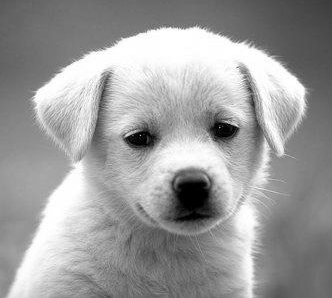
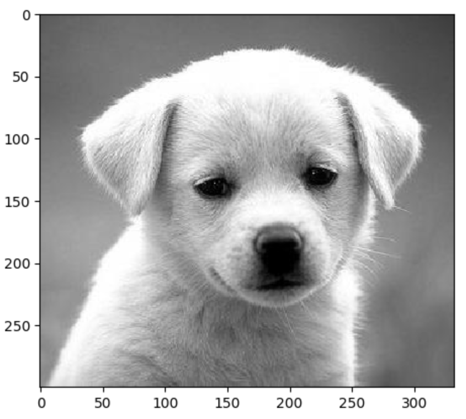
The original image used in this project is:
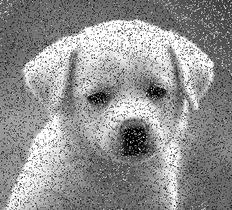
Add Noise
Using Salt-pepper, randomly changing the value of pixels to [0,0,0] or [255,255,255].
Noise Reduction
Average Smooth
Using NS5 to caculate the average value.
Median Smooth
Using NS9 to caculate the median value. Now using Median Smooth on the noised version.

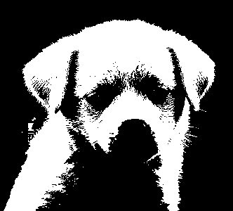
Gray-Scale to Binary
The most common way is to set a thresholding, if the value of pixel is larger than that thresholding, setting the value of pixel as [255,255,255], if not, setting it as [0,0,0].
There’re two more methods which can achieve the goal, the first one is P-Tile, which means the pixel with the top x% value can be converted to white, others should be converted to black.
And the second one is Iterative Thresholding.
- Setting T as a random number, and appling the T to the common thresholding method.
- Caculating the new thrsholding T’ = 1/2(a1+a2).
a1 = the average of the value of pixel which is larger than T,
a2 = the average of the value of pixel which is smaller than T, and caculating the absolute value of (T-T’). - If the result is larger than 1 (whatever), using T’ as T to continue the above loop, until the result is smaller than 1, finally, the T’ in last loop should be the thresholding in converting.
Label-Component
The main purpose of Label-Component is to detect the number of components the image has. It can be only applied to binary images. The initial value/label of the image is: the label of white part is 1, the label of black part (usually background) is 0, we usually say the pixel with label 0 is invalid, and when scaning the whole image, there’re three conditions should be followed, for e.g., when scaning img[i][j]:
- if the label of top and left pixel are invalid, the label of img[i][j] = label ++
- if one of the label of top and left pixel is invalid, the label of img[i][j] = the label of the valid one.
- if both the label of top and left pixel are valid,
If the label of top = the label of left, the label of img[i][j] = that label.
If the label of top and left pixel is different, the label of img[i][j] = the smaller one. And set the equivalent.
In this project, to implement this part, my method is:
- Creating a Matrix with the same size of image. Each position of matrix corresponds to each pixel of image.
- Initilizing that matrix with label 0 and 1.
- Creating a list to record the equivalent.
- If matching the 1st condition above, appending the new label to the list.
If matching the 3rd condition above, for e.g., the label of top pixel is 5, the label of left pixel is 4, then setting list[5] = 4. In other words, the larger label should be the child, the smaller label should be its parent.
For e.g., after scanning the whole image for 1 time, the list = [0,1,2,2,3,4], which means list[0] = 0, list[1] = 1, list[2] = 2, list[3] = 2, list[4] = 3, list[5] = 4. Let’s do the second scan, starting from the tail of the list, if list[5] != 5, using 4 as index, list[4] != 4, using 3 as index, list[3] != 3, using 2 as index, list[2] == 2, that’s it, and setting list[5] = 2. Finally after second scan, list = [0,1,2,2,2,2], which means label 2,3,4,5 should be in one set, in other words, should be one component.
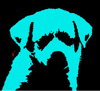
The coloring part is easy, just setting some random color to different components. Let’s see the result.
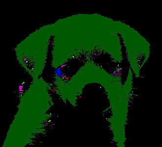
We can see, there’re tons of noises in this image. To get a better performance, we’d better to smooth the binary image before labeling.

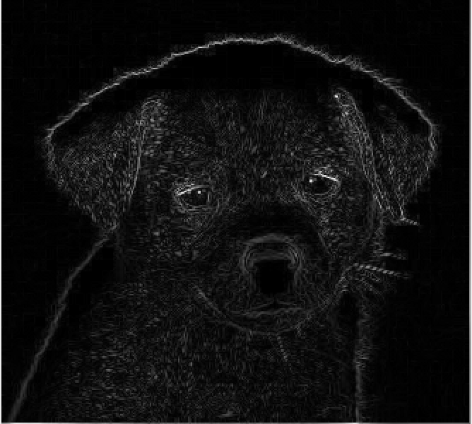
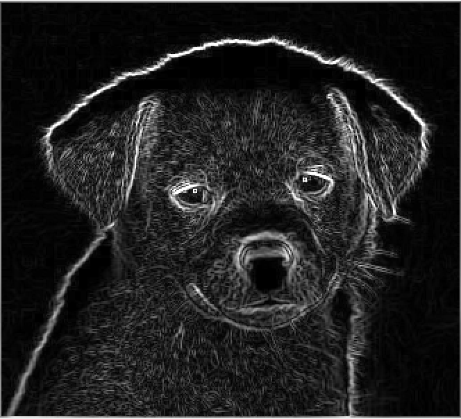
Sharpening
The main idea of image sharpening is, checking the adjacent area and computing the variation.
Robert’s Operator
[0,-1,1,0]+[-1,0,0,1]
Meanwhile, we can set a thresholding based on Robert’s Operator.
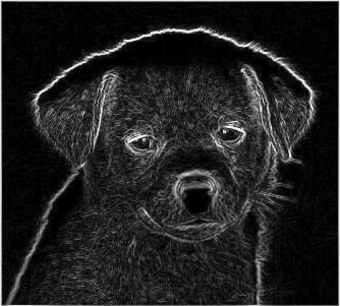
Sobel Operator
x = [1,2,1,0,0,0,-1,-2,-1], y = [1,0,-1,2,0,-2,1,0,-1], result = math.sqrt(x**2+y**2)
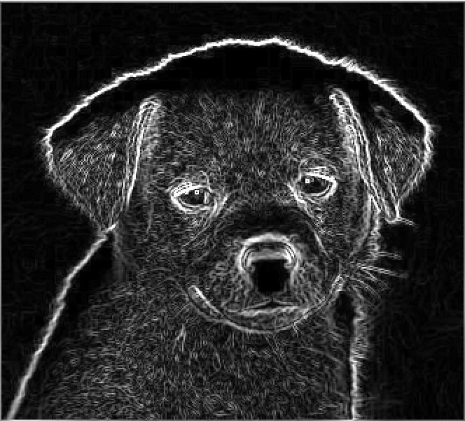
Prewitt Operator
r1 = [-1,0,1,-1,0,1,-1,0,1], r2 = [1,1,1,0,0,0,-1,-1,-1], result = math.sqrt(r1**2+r2**2)
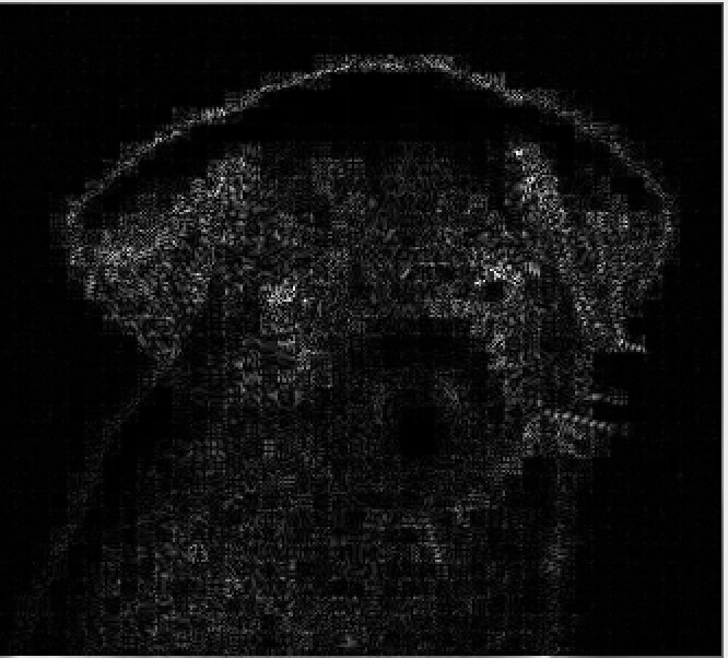
Kirsch Operator
r3 = [0,1,1,-1,0,1,-1,-1,0], r4 = [1,1,0,1,0,-1,0,-1,-1], result = max(r1,r2,r3,r4)
Laplacian Operator
ori1 = [0,1,0,1,-4,1,0,1,0], ori2 = [1,0,1,0,-4,0,1,0,1], new = [1,1,1,1,-8,1,1,1,1] or [-1,-1,-1,-1,8,-1,-1,-1,-1]
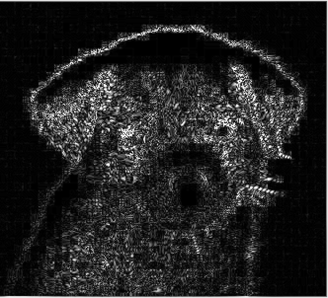
We can not say which one is better, it depends on different cases.
Pyramid
Downsampling
The main point of pyramid is downsampling the image. Firstly, we should add dummy data to resize the image to 2**n rows and 2**n columns, then downsampling the original image to the new image with 2**(n-1) rows and 2**(n-1) columns. Continuing the steps above, the shape of the image will be smaller and smaller.
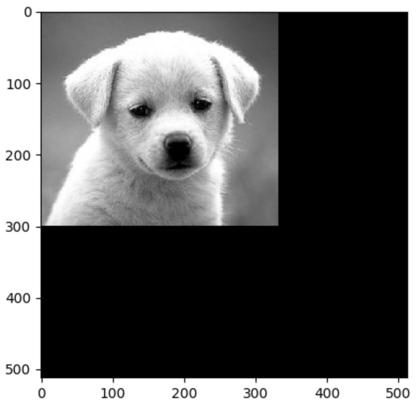
The shape of original image is [300,332,3]
After reshaping the image, the shape of image is [512,512,3]
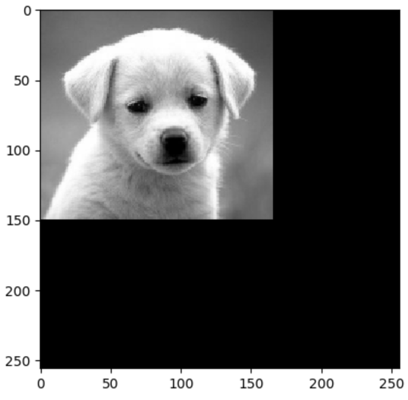
Downsampling 1 time to the size [256,256,3]
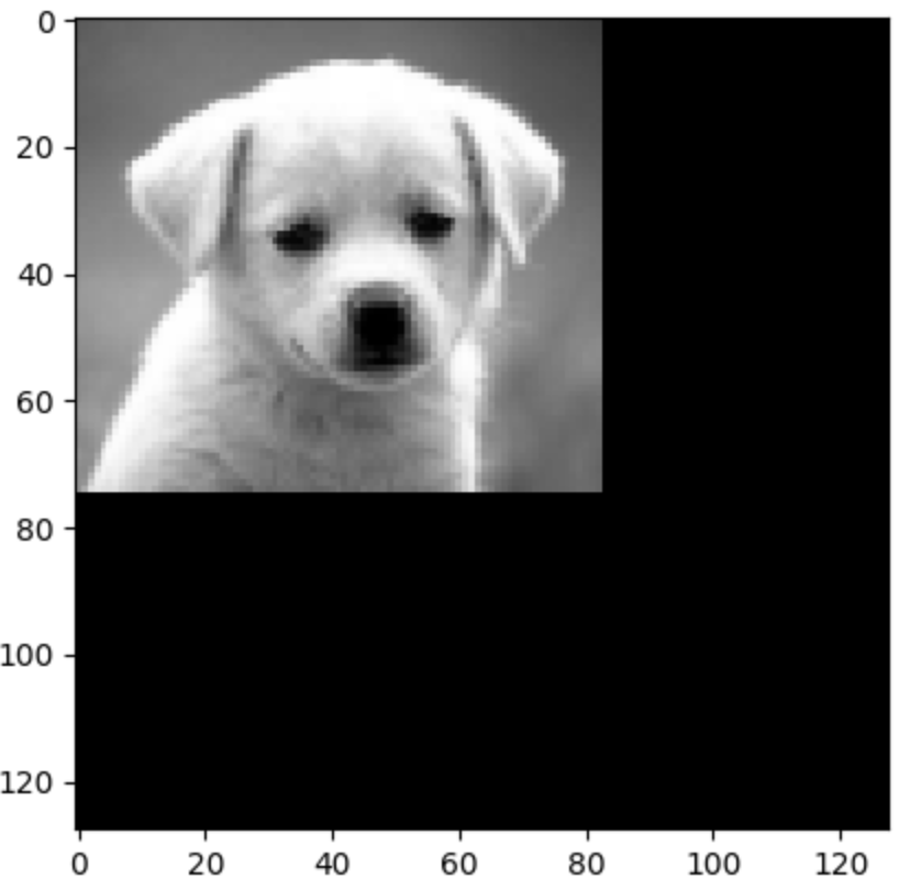
Downsampling 2 times to the size [128,128,3]
Downsampling 3 times to the size [64,64,3]
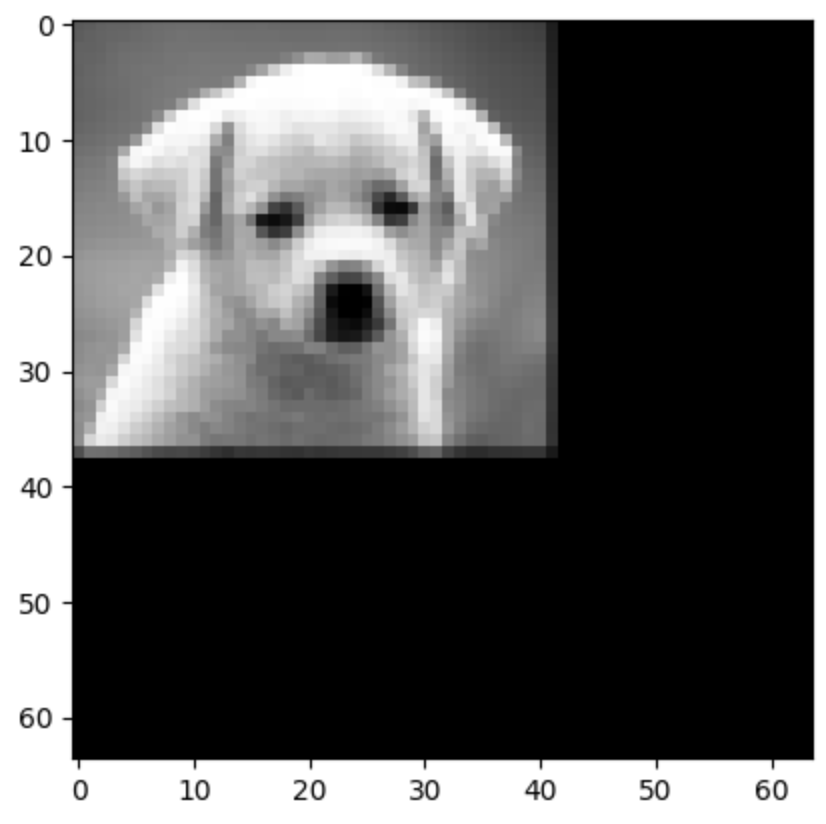
Upsampling: Zero Order
# The original image is:
[[3 5 7]
 [2 7 6]
 [3 4 9]]
# Padding with 0:
[[0 0 0 0 0 0 0]
 [0 3 0 5 0 7 0]
 [0 0 0 0 0 0 0]
 [0 2 0 7 0 6 0]
 [0 0 0 0 0 0 0]
 [0 3 0 4 0 9 0]
 [0 0 0 0 0 0 0]]
# After applying mask[1,1,1,1]:
[[3 3 5 5 7 7]
 [3 3 5 5 7 7]
 [2 2 7 7 6 6]
 [2 2 7 7 6 6]
 [3 3 4 4 9 9]
 [3 3 4 4 9 9]]
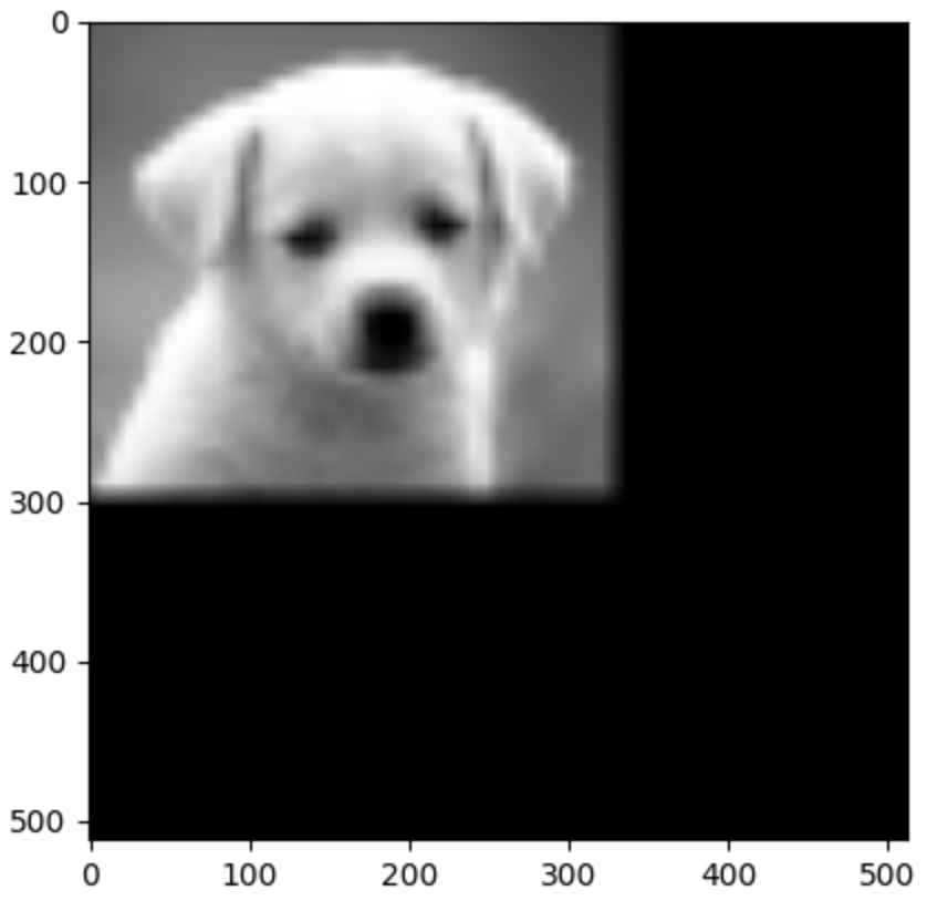
Using Zero-Order 3 times to upsample the image to the original size [512,512,3]

Upsampling: First Order
# The original image is:
[[3 5 7]
 [2 7 6]
 [3 4 9]]
# Padding with 0:
[[0 0 0 0 0 0 0]
 [0 3 0 5 0 7 0]
 [0 0 0 0 0 0 0]
 [0 2 0 7 0 6 0]
 [0 0 0 0 0 0 0]
 [0 3 0 4 0 9 0]
 [0 0 0 0 0 0 0]]
 # After appling mask[0.25,0.5,0.25,0.5,1,0.5,0.25,0.5,0.25]:
 [[3 4 5 6 7]
  [3 4 6 6 7]
  [2 4 7 7 6]
  [3 4 6 7 8]
  [3 4 4 7 9]]
Using First-Order 3 times to upsample the image to the original size [512,512,3]
Steganography
The main purpose of steganography is encoding the text information into a ‘cover image’ and decoding it.
The ‘cover image’ I use is as follows:

Embed secret information/TEXT into a ‘cover image’
Firstly, we need to convert strings(secret information/TEXT) to the binary format based on their ascii, then we need to change the last n bits of the value of each channel, the channel of this image is [R,G,B].
If we set n as 1, which means we only change the last 1 bit of the value of the channel to store the binary information of the TEXT, the new image is as follows:

We can not see any difference between this one and the original image.
Let’s try to set n as 2 and 3.


we still can not see the difference. Actually for the right one(modify last 3 bits), there’s very little differences.
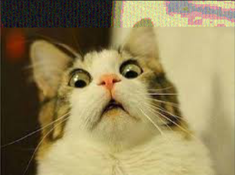
If we set n as 4 and 5.


Now we can see that there’s something on left top and right top.
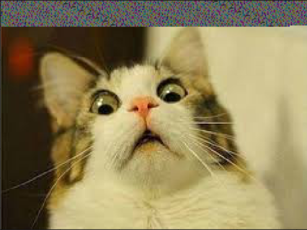
Setting n as 6 and 7.

Now it’s very clear that there’s something happened on the image.
Setting n as 8.
Now the top part is totally trash for visulization.
Extract secret information/TEXT from a ‘cover image’
Now we can extract the last n bits of each channel to get the binary information of the TEXT,(we need to take care of the last channel because maybe we do not need all the last n bits), and then convert the binary information to text.
The secret information is as follows:
And after extracting, the information is as follows: